 Now that we walked through all the steps of reducing power consumption from the start through first tests, reducing consumption, optimized tests and adding a RTC including the problems of waking up from sleep via interrupt, adding a 24AA256 EEPROM as external memory. and using it in page mode it’s time to make a more useable system from what we have.
The first steps are increasing the datalogging interval and then using a supercapacitor.
Increasing the datalogging interval
First we change the datalogging interval from one second to one minute. This is because when we want to have the system log environmental data like e. g. room temperature or solar irradiation we don’t need the data of every second.
 The diagram shows what happens. Total uptime has increased from 9400 seconds (= 2 h 36 min) to 799 minutes (= 13 h 19 min). On the other hand total amount of logged data has gone from 9400 down to 799. This is because with the longer logging interval the influence of the losses during sleep increases. I think this is somewhat the limit of the “2×4700μF capacitor system”. Powering the ATmega with these capacitors was sort of a testbed. Now it’s time to have more energy for longer uptime.
Supercapacitors
The next tests are done with a 1F 5.5V supercapacitor from Panasonic. Total system energy is increased tby a factor of around 100. In a first test let’s look at the self-discharge rate of the capacitor.
 The diagram on the left shows my own measurements over one week. I don’t know why the voltage dropped quickly at the beginning. The capacitor was brand new at this test. Then voltage decreases very slowly. While writing this post I measured the capacitor’s voltage again as it was only lying around since the measurements above. The voltage is 3.49V after 554.5 hours (≈ 23 days)! This will give us enough time for our datalogging system. Now the next step is to run the system from this capacitor…
First tests with 1F capacitor ![:-)]()
Having the system run with more energy increases total uptime and thus, more memory for storing data is necessary. So I switched from the 24AA256 (32KB) EEPROM to the 24AA1025 (128KB). The first test was done with two of them giving a total of 256KB EEPROM in only two small 8-pin DIP packages. I went back to a logging interval of 1s to have total uptime shorter (don’t have to wait so long for the test to run). EEPROMs are written in page mode with 64 bytes at once. The 24AA1025 has a page size of 128 bytes but I wanted to keep the old settings for comparability.  The diagram on the left shows the result: There isn’t enough memory! The system has run 131,072 seconds until memory was completely written. This is: 36 hours and 24 minutes. After this time supply voltage dropped only down to 4.15V (!) so total uptime would be much longer!!!
The next test is done with a total of 512KB EEPROM memory. Here is a picture of my setup:
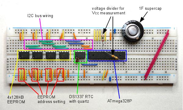
With this big memory I had some addressing problems. The solution to this is documented in this post. Now I can address the whole memory with a linear address that walks through all 524,288 memory bytes!
With the 1F supercap the system was running three days with a measuring interval of 1s. Then memory was full. Supply voltage dropped to 3.34V so there is a lot of potential for more 
Downsizing to 0.1F
The next tests are done with a 0.1F supercapacitor to have uptimes shorter. This will give me not-so-lengthy testing.
 This diagram shows the result for 1s measuring interval and 256KB external EEPROM (two 24AA1025). Total system uptime is 18.4h. The comparable “small” system with 2×4700μF (≈0.01F) had a total uptime of 2.6h. At a first glance, increasing the capacitor by a factor of 10 should also increase total uptime the same way. Here uptime rises only by a factor of 7. OK, where are the additional losses? In the present system we have more components (the 24AA1025) that also need energy. So the losses are higher than before. Personally, I also think there is an issue with the 0.1F supercap as the voltage drops very fast at the beginning. This also makes uptime shorter. So, overall the results are realistic. For a 1F capacitor total uptimes should rise again by 7 to 10.
Designing a “real” system
For a “real life” system 1F capacity should be a good choice to have the system running for some days which is a common dimensioning in standalone pv system, see e. g. here. For the “real” system there will be additional hardware to measure whatever you want. These components should be switched off during sleep (as I did it with the voltage divider for Vcc measurements). For such a small system a supercap is a good choice. They keep the energy for a much longer time than I personallly thought (and many people said). So to bring something like this to real life simply build a test sample, write the code and use all the hints in this series of posts.
Next steps should be answering the question of how to get the data out of the system and perhaps having a user interface. To me, this series is now cloed at this point. I was able to show how efficient a ATmega driven system can be compared to the standard mode (not using sleep modes). Having the controller run only when there’s something to do and keeping it in the deepest possible sleep mode all the other time can increase energy efficience by a factor of 1000 depending on your application.
Enjoy
heliosoph
The post Arduino powered by a capacitor – towards a real system appeared first on heliosoph.


